
Migration of seismic data moves dipping events to their correct positions, collapses diffractions, increases spatial resolution and is probably the most important of all processing stages. Migration theory has been long established but restricted computer power has driven the industry to a bewildering array of ingenious methods to perform and enhance the accuracy of migration. It could be argued that much of the past research has been directed towards doing migration less wrong rather than doing it right. Certainly there has been more research into migration algorithms than the critical factor of determining the correct velocity model to use. With today's availability of cheap computer power modern practice tends towards doing migration as correctly as possible rather than as cheaply as possible. Most migration algorithms have good points and bad points and work better in some data areas than in others. As in much of processing the choice of which migration algorithm to apply is rather subjective. In this section we introduce the basic theory of migration and discuss the various methods and terminology which have built up over the last 30 years. Yilmaz (1987) and Bancroft (1998) contain many further details and examples of migration.
The theory of zero-offset migration is important since the stacking process simulates a zero-offset section as well as attenuating noise and multiples. The migration process is referred to as poststack migration or zero-offset migration. If the stack does not produce a good approximation to the zero-offset section then prestack migration must be performed prior to stacking. Due to the data volumes involved, prestack migration takes at least the fold of the data longer to compute than poststack migration.
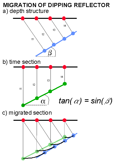
The adjacent figure (a) shows a zero-offset seismic experiment conducted over a constant velocity medium. Sources and receivers are marked by red dots. The image of dipping reflector dip b results in seismic section (b) where the reflection point is plotted in green below the receiver at a time equal to it's reflection time (t1-t4). On the seismic section, the dip a and position of the reflector are incorrect and an interpretation of this section would be in error. The equation shown in (b) relates the dip before and after migration. The maximum dip on the seismic section of 45o corresponds to a reflector dip of 90o. By taking a semicircular arc equal to the travel time from each of the recorded positions and constructing a line at tangent to the arcs the true migrated position of the reflector is discovered (c). The process of migration makes the resulting image look like the true geological structure. Migration is sometimes also called imaging. The migration process has moved the reflection up-dip and the migrated segment (blue) is steeper and shorter than the reflection segment (green). Frequencies will be lower on the migrated segment. In the diagram the velocity is assumed to equal 1 so the vertical axis of time and depth are interchangeable. For the migration to be correct (figure (a)) the vertical axis of (c) would be in depth and would require the velocity to be known (in order to convert from the recorded time section to the migrated depth section).
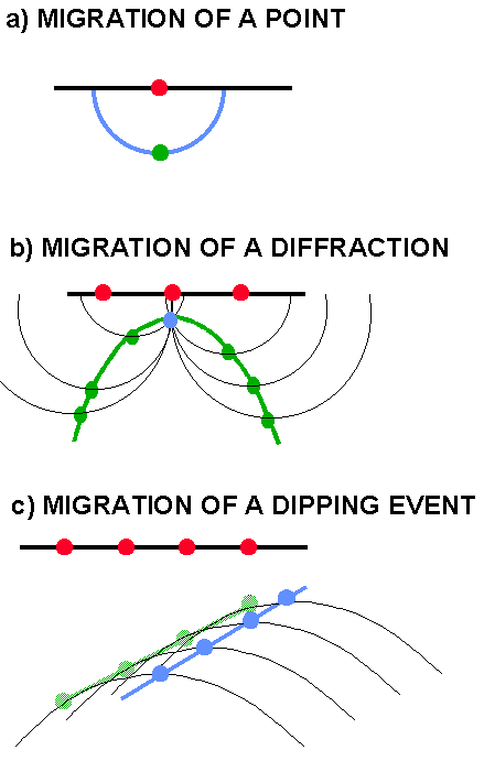
The earliest methods of migration by hand used the semicircular construction shown in the adjacent figure (a) for the migration of a single point shown in green. The migrated result shown in blue is a semicircle in a constant velocity medium. This result is also called the impulse response of a process and is especially useful since a seismic section can be considered to consist of a series of spikes - the migrated reflectors will occur where the semicircles constructively interfere. This is called Hagedoorn migration where the amplitude of the spike on the input time section is distributed along a semicircle on the output migrated time section. Destructive interference will cancel out noise, but sometimes residual semicircular smiles are seen in the resulting section as a result of noise.
In (b) of the adjacent figure the constant velocity semicircle construction is used to migrate a hyperbolic diffraction curve (green) to it's migrated position (blue point) where the semicircles interfere. An alternative method would be to sum the amplitudes along the hyperbola and place the summed amplitude at the apex. This latter form of migration formed the basis for the first computer algorithms and is called diffraction summation, diffraction stack or more generally Kirchhoff migration. In the figure (c) a Kirchhoff summation is illustrated for migration of a dipping event. The zero-offset section is considered to be a superposition of diffractors at each time sample (Huygen's Principal). The diffractors interfere to form coherent events and individual diffractions may be visible at discontinuities such as faults. At each output time migrated position (shown by the blue dots and line) the amplitudes of the input zero-offset time data (green dots and line) are summed along a series of hyperbolas controlled by the velocity field (some of which are illustrated). Maximum amplitudes will occur at the migrated event, otherwise the amplitudes will be minimal.
A major difference in migration algorithms arises from the way the velocity field is utilised. In the early 1970's when migration algorithms were being developed the computer power was so limited that several approximations were introduced in order to get programs to run in anything like a reasonable time. These assumptions led to time-migration - a process which collapses diffractions and moves dipping events toward the true position but leaves the migrated image with a time axis which must be depth converted at a later stage. Time migration assumes that the diffraction shape is hyperbolic and ignores ray bending at velocity boundaries.
Depth Migration assumes that the arbitrary velocity structure of the earth is known and will compute the correct diffraction shape for the velocity model. The data are then migrated according to the diffraction shape and the output is defined with a depth axis (although results are often stretched back to time to enable comparison with time migrations). If the velocity model for the depth migration is incorrect then the migration will be incorrect and the error may be difficult to detect if the migration is performed post-stack. Prestack depth migration will provide an error estimate of the migrated result. Depth migration typically takes 10 times longer to run than time migration and is very sensitive to velocity errors (required to be within 1%) and may require many iterations which further increases run time. Poststack depth migration is often performed for reasons of economy but prestack depth migration is almost always required since it is almost impossible to define an accurate velocity model using purely poststack processing.
Historically the development of time migration proceeded in advance of depth migration mainly because of computer technology. Also the sensitivity of depth migration to the velocity model (basically you need to know the answer before you start) can easily lead to very poor and misleading results. The time-migration is always incorrect, but in practise the results turn out to be resilient to a large variation of different velocity models and geological structures and can be very useful for an initial interpretation such as for building models for depth migration. The interpreter will often treat a time-migrated section as a geological image. While this is wrong it is often "fit for purpose" in oil exploration. Depth migration may be considered to be an "appraisal or development" technology whereas time migration may be considered an "exploration" technology. A time-migration can also be easily compared to the input stack section since they have the same vertical axis. Time migration is very fast and is robust to errors (sometimes up to 10%) in the velocity model. Further, errors in the shallow velocity model do not affect imaging of deeper structures.

Judging the "correctness" of a time migration is a rather arbitrary process but lateral velocity variations will cause positioning errors as indicated by image rays. An image ray, as shown in the adjacent figure for a single diffraction point, is normal to the recording surface and will show the lateral positioning error due to time migration. Unlike rays which indicate the direction of propagation, the image ray has no physical meaning. If an interpreter is at all worried about the positioning of data prior to drilling a well then a depth migration should always be performed. Surprises may result - particularly in 3D where structures can change dramatically in depth.
Judging migration results should always be done in conjunction with an interpreter. Note that with depth migration it is easier to force an incorrect interpretation into the final migrated result - the so called "model in model out" problem. If suitable constraints can be placed on the velocity model then depth migration will produce the "correct answer", although this judgement is also subjective. A depth migrated section should not tie the well data in depth because the correct migration velocity is not the true earth velocity. However, the migrated depth section can be stretched vertically to tie the well data whereas the time migration would require a lateral and vertical shift.

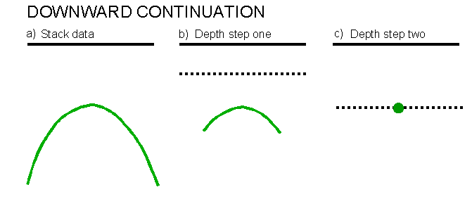
Modern migration techniques are solutions of the one-way scalar wave equation which is a partial differential equation representing the rate of change of a pressure field in space to changes in pressure over time. The equation does not allow for multiple reflections, converted waves or noise although alternative wave-equations exist to cover these modes of wave propagation. The exploding reflector technique is one way of visualising zero-offset wave-propagation in which the sources are fictionally placed on each reflector and are exploded simultaneously at time zero. The wavefield propagates to the surface at half the true velocity. Using this model migration can be considered as the reverse process where the wavefield at the surface is carried deeper into the earth using the solution to the wave equation. This process of downward continuation is the mathematical equivalent to lowering the receivers into the earth. After the first downward stage the wavefield at t=0 is saved as the reflector shape at the particular depth. This is called the imaging stage. The wavefield resulting from the first stage is then downward continued and imaged. The method proceeds recursively until the maximum depth. Consider a diffraction hyperbola. As the wavefield is continued into the earth the diffraction will collapse as the apex is approached, the migrated image is correct when the apex is reached.
Kirchhoff and phase-shift migrations are solutions of the scalar wave equation and can also be considered mathematically as consisting of downward continuation and imaging stages.
Finite difference solutions of the wave-equation can be used to efficiently implement downward continuation and can handle laterally varying velocity fields. The method of finite differences is simply a way to compute derivatives and second derivatives in a computer. Several solutions to the wave-equation exist and contain different mathematical approximations in order to obtain the solution. The approximations dictate the characteristics of the migration when applied in practice. Finite differences can be used to implement both steep dip depth migration solutions (by retaining the thin-lens term of the scalar wave-equation solution) and dip-limited time migration solutions. These latter are usually referred to as the 15 degree and 45 degree assumptions. A further frequency domain solution provides a 65 degree dip limitation sometimes called FX or omega-X migration. The run time increases with dip accuracy. The actual dip limits migrated will depend on velocity, depth step, trace spacing and sampling interval. Migrations may be cascaded so that several 15 degree migrations are run with incremental portions of the velocity field and the results added to achieve dip limits of nearly 80 degrees. The 15,45 and 65 degree solutions are called implicit solutions after the method of solving the wave-equation developed by Claerbout.
Alternative steep dip depth migration schemes such as reverse time migration use a finite difference solution to a two-way wave equation which can include multiples. The full reverse time solution can be very accurate but very slow.
Dispersion is always associated with finite difference migration solutions and this can further limit the dip accuracy of the method.
A category of modern high accuracy migrations which solve the wave-equation by applying spatially varying convolution operators in the FX domain. These should not be confused with the finite difference 65 degree approximation which is also sometimes called FX or omega-X migration. The explicit solutions are usually applied to steep-dip depth migration solutions, particularly for 3D migration.
Migration in the F-K domain is an important method since it is by far the quickest assuming constant velocity and is accurate to 90o. FK migration is also referred to as Stolt migration after its inventor. In the previous discussion it was shown how events of the same dip in the time domain map to radial lines in the FK domain. The method works by transforming the data to the FK domain and applying the migration equation tan(a )=sin(b ) which shifts the data vertically on the frequency axis only to transform the data to the migrated dip. Following inverse transformation the migrated solution is obtained. Stolt later introduced a method of accommodating vertical velocity variation by stretching the time axis before migration to make the reflection events appear as if they were recorded in a constant velocity medium. This process is called Stolt stretch. In some implementations a lateral stretch is also employed which makes the FK migration tend towards a depth migration. Sometimes a Cascaded FK Migration is performed in which the input time data is FK migrated many times with constant velocities and the results merged together.
Another migration implemented in the F-K domain is the phase shift or Gazdag migration (after its inventor). This is a downward continuation algorithm in common with finite-difference methods except the downward continuation is carried out by a phase shift in the FK domain. As originally implemented the method can handle only a vertically varying velocity. A phase-shift-plus interpolation or PSPI migration was later introduced by Gazdag to handle lateral velocity variations. This method performs several migrations with laterally constant velocities and interpolates the final migrated results. Depth migration and imaging of turning rays is also possible.
The commonest hybrid algorithm is a cascaded time migration technique sometimes called Residual Migration and can be applied in 2D or 3D. The method exploits the steep dip but constant velocity assumptions of FK migration with the dip-limited but lateral velocity handling characteristics of a finite difference migration. The data are first migrated with an FK migration using the lowest velocity found in the section (e.g. 1500m/s). The FK migration will partially collapse diffractions so the flanks are no longer as steep. A residual migration is then run with the finite difference method using a computed residual velocity which can vary laterally and vertically. This method can be attractive in practise and fast.
Some hybrid or pseudo-depth migration algorithms exist which either apply approximations of the thin-lens term (finite difference solution) or attempt to partially shift the diffraction apex according to lateral velocity variations (Kirchhoff solution). These algorithms are not used currently by contractors, but care should be taken with older vintages of data which may have been migrated with these methods since they can lead to unpredictable results.
Modelling (creating a seismic section from a geological model) is often seen as the inverse of migration.
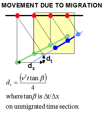
For a constant velocity migrated time section it is possible to derive useful relationships which indicate how far a point will move laterally in space or time. This is illustrated in the adjacent figure where dip angle a is measured on unmigrated time seconds in ms/trace, v is the medium velocity, dx is the horizontal displacement dt is time displacement, and t is the two-way travel time to the dipping event. Yilmaz gives further equations for migration angle b and time displacement dt.
The following table copied from Yilmaz summarises results for dips of 10ms/trace and 25m trace spacing.
|
t(s) |
v(m/s) |
dx(m) |
dt(m) |
a (ms/trace) |
b (ms/trace) |
|
1 |
2500 |
625 |
0.134 |
10 |
11.5 |
|
2 |
3000 |
1800 |
0.4 |
10 |
12.5 |
|
3 |
3500 |
3675 |
0.858 |
10 |
14 |
|
4 |
4000 |
6400 |
1.6 |
10 |
16.7 |
|
5 |
4500 |
10125 |
2.82 |
10 |
23.0 |
For the examples shown above the displacements can be quite large for example at 4s the event moves more then 6km laterally following migration. Also since the horizontal displacement is proportional to v2 then velocity errors quickly become critical. The results indicate that the seismic section must be recorded to sufficient time and of sufficient depth to record contributions of all events required in the final migrated section. For example if only the beige area of the previous figure were recorded then only a portion of the migrated reflector in blue would be correct or would stay on the section following migration. In practice sections are recorded with a migration aperture of several kilometres. The choice of migration aperture, particularly for 3D surveys, will be a critical parameter decision as it can increase costs considerably. Usually previous vintages of 2D data are used to determine likely dips and velocities to be encountered and migration aperture and recording time calculated accordingly.
As has been previously seen the stacking process does not perform correctly for dipping reflections and smears events with consequent loss of resolution. Migration should therefore be performed prestack for ultimate resolution.
Even if a 2D survey is acquired in a perfectly dip and strike direction for a 3D structure there will always be a mistie between the migrated 2D and 3D structures. In addition for moderate geological structure much of the energy on a 2D section will be recorded out of the plane (sideswipe). Appropriate migration of a 3D survey will cancel any sideswipe events and provide a clean image of geological structure to be interpreted. Generally most of the 2D migration schemes can also be used in 3D. For a constant velocity in 2D a point reflector will produce a hyperbolic diffractor. In a constant velocity 3D medium a point reflector produces a hyperboloid diffraction volume which yields a hyperbola when vertically cut in a 2D direction. The perfect impulse response of a 2D migration is a semicircle, for 3D migration it is a hemisphere. A horizontal slice through the hemisphere will be a circle - this technique is used to evaluate the performance of 3D migration. In 3D a Kirchhoff migration can simply weight and sum all the amplitudes and place them at the apex as in 2D migration. While accurate this method is expensive so processors have, as ever, devised a series of approximations which may be used to decrease run time and also, consequently, accuracy.
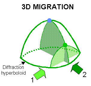
Until the early 1990's most 3D surveys were migrated with the so called two-pass method. For constant velocity the data can be migrated in the inline direction collapsing one dimension of the hyperboloid to a hyperbola. This is shown on the adjacent figure by the light green colour. The data are next migrated in the orthogonal (crossline) direction to collapse the residual hyperbola to a point, shown blue on the adjacent figure. Assuming constant velocity any 2D time-migration method can be used in a two-pass scheme, but the commonest used was the 45 degree finite difference migration. The data were usually interpolated in the crossline direction before the second migration so that the crossline spacing is identical to that of the inline. Occasionally the first migration was run in the crossline direction. For a vertically varying velocity field errors are introduced with the two-pass method since during the first pass the deeper parts of the diffractors will be migrated with velocities at the apex of the hyperbola not the hyperboloid. For shallow dips and generally for time-migration these errors are not severe, and may well be less than uncertainties in the velocity model. The method is flexible since different velocity percentages can be used for each direction and velocity testing is rapid since it is only performed in 2D. The two-pass method is now only of historical interest.
A 3D migration which accommodates vertical and lateral velocity variations can be accomplished by one-pass migration methods which became standard towards the mid 1990's as contractors learned to implement them cheaper than the 2-pass methods on faster hardware with large memory. The commonest original method was a finite-difference approach known as splitting in which the downward continuation was carried out at each depth stage in the inline and crossline directions followed by the imaging stage. The migration error in this method occurs at 45 degrees to the inline and crossline directions which is also towards the dip limits of the finite difference migration. The two-pass approach shows similar impulse response. Much research has been directed towards developing a one-pass migration with a circular impulse response - a migration with equal steep dip response at all azimuths. Methods include phase corrections at the 45 degree azimuths (Li correction implemented by CGG) or in the FX domain the use of circular factorisation of impulse responses which are then convolved with the data (Hale-MacLennan techniques). 1-pass phase shift and Kirchhoff migrations are also available.
HYBRID-MIGRATIONS
A residual migration is also sometimes used in which a 1-pass FK migration is followed by a 2-pass finite difference approach. The method retains the flexibility of 2-pass migration velocity analysis and the accuracy of the one-pass scheme.
All migration algorithms require a velocity model. Choice of the velocity model is critical and may differ between algorithms. For poststack migration the optimum velocity model is particularly subjective since it is difficult to judge the quality of the migrated results. Time migration will tolerate a certain amount of error in the velocity model. The commonest way to build a velocity model for time migration is to take the picked stacking velocities (assuming they are equal to Vrms) and smooth them sufficiently that the interval velocity model (from DIX conversion) is smooth and approximately resembles the geological structure. Almost always in modern processing DMO or prestack time migration will have been applied to attempt to remove the dip-dependence of stacking velocities. For time migration to be worthwhile the velocity model can vary smoothly in depth and very slowly laterally.
Once the velocity model has been constructed, trial lines are migrated with the velocity model and arbitrary percentages of it and the interpreter will pick the most appealing section. Typically percentages will vary from 90% to 105% of the original velocity model. For a 3D survey the best method is to migrate the entire volume with the different velocity percentages although many contractors will attempt to only migrate 2D sections. Costs for the full 3D process are reduced by bandlimiting the data to 40Hz and migrating on a coarse (e.g. 50m) grid. Alternative methods exist for 3D data but are all approximations and should be avoided.
In 2D or 3D the processor and interpreter will inspect the different sections and pick the optimum velocity percentage which may vary spatially for time migration as long as the variation is smooth. Things to look out for are collapse of diffractions, imaging of faults (breaks should be sharp not smeared) and meaningful geological features such as synclines or anticlines. There is no substitute for experience. The best way to begin is to compare the 90% velocity migration with the 110% migration. The former should be undermigrated and the latter should be overmigrated - the correct answer should be somewhere between the two. Undermigrated sections will show uncollapsed diffractions and overmigrated sections should show more smearing and smiles. A synthetic showing a horizontal event, dipping event and diffractor in a constant velocity medium follows.
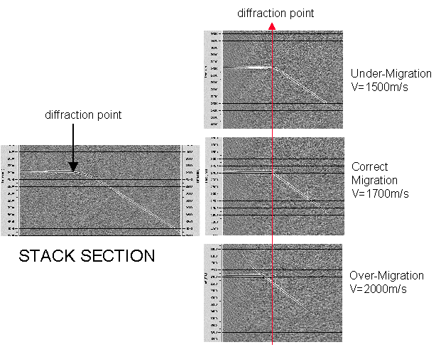
In the previous diagram three constant velocities are tested in order to obtain the optimum velocity. The red line shows that spatial mis-positioning will occur if an incorrect migration velocity is used. As previously shown this mis-positioning will be greater for higher velocities and steeper dips. Note that the migration is not perfect even with the correct velocity. This is because the aperture of the diffraction is limited. For a portion of a 2D section, migration with a suite of constant velocities may be a viable way of determining optimum migration velocity, but this method is rarely used in practise since it is expensive. Click here for a movie which shows an example dataset migrated with a suite of constant velocities.
In practice for the North Sea stacking velocities are usually picked too fast and optimum migration is achieved by 95% or 97% of the smoothed stacking velocities. Sometimes however a slow velocity trend may have been picked and 105% provides the optimum migration result. As ever, testing is required. Note also that the same migration algorithm for velocity testing should be used for the production migration since different algorithms treat the velocity field in different ways. This is particularly true of finite-difference migration which tends to leave the data with an undermigrated appearance.
Velocity model building for depth migration is a more complex procedure and is discussed in a further section (yet to be completed).
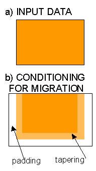
Prior to migration the data are expected to have been pre-processed to minimise noise and multiples. High levels of noise or spikes may be a particular problem and will cause smiles on the resulting section. Amplitudes of the deeper 500ms and edge 100 or so traces are often tapered to zero prior to migration to avoid edge effects and the migration aperture. Sometimes trace padding is also applied by adding zero samples to the ends of traces. Some processing systems perform padding and tapering within the migration process and on others it must be applied separately. Some migration algorithms are very robust to quite high noise levels (particularly in 3D) so noise reduction such as dip filtering may not be required. In many cases noise reduction can be carried out effectively following migration.
Migration is particularly prone to problems with spatial-aliasing since the dip-reversal affect of aliased data means the migration does not know which way to move the data. Some is moved in the true up-dip direction but some of the energy will be moved or dispersed in the down-dip direction. Data should be recorded at sufficient trace spacing to prevent aliasing prior to migration. A 12.5m CMP spacing is commonest and this is adequate for most frequencies and dips encountered in the North Sea. Data with 25m CMP spacing (such as a crossline in a 3D survey) may be interpolated to one with a 12.5m spacing prior to migration (a variety of methods may be used). Finite difference migration typically requires finer trace spacing to prevent additional dispersion caused by approximations within the migration operator itself.
Choice of migration algorithm is data and contractor dependant and usually is extensively tested to obtain optimum results. Many migration algorithms exist and some are be more expensive than others to apply. Explicit FX, Phase shift or Kirchhoff algorithms are the best for time migration, and Kirchhoff migration is preferred for prestack depth migration.
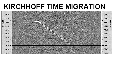
The previous theory section introduced migration as a process which moves dipping events by summation of diffractions in an easily understood method called Kirchhoff Migration. Kirchhoff Migration is the most flexible migration algorithm and can be implemented in 2D and 3D, pre- and poststack and as a time or depth migration. Kirchhoff migration can also be implemented to migrate shear and converted waves, dip filter and interpolate the input data, and cope with spatially aliased data. Most sane people understand migration algorithms by reference to Kirchhoff migration. The adjacent figure shows the test synthetic section migrated with the Kirchhoff migration. Click here for an example section migrated with the Kirchhoff algorithm. Despite the migrations high accuracy and flexibility, the Kirchhoff migration is rarely used by contractors for time migration. This is because other techniques can be run cheaper - but sometimes at the expense of accuracy. Almost all prestack depth migration is performed using the Kirchhoff technique.
To preserve the amplitude and phase of the input data it must be corrected for geometrical divergence, a directivity factor (to correct for angle dependence of amplitudes) and a wave shaping factor prior to migration. For 2D data the latter is a filter with a 45o phase shift and amplitude spectrum proportional to square root of frequency (square-root derivative). For 3D data the shift is 90o with amplitude proportional to frequency (derivative). Most Kirchhoff implementations (e.g. PROMAX) apply these corrections internally within the migration process. When using the AHC Simon processing system the data should be pre-processed with the DIFR routine to apply the appropriate corrections.
For a velocity function which smoothly varies vertically the diffraction hyperbolas should be constructed using Vrms at the apex and this also tolerates moderate lateral velocity variations. For complex velocity variations a depth-migration is required and the diffraction curves are calculated by ray-tracing.
The principal parameters for Kirchhoff Migration are trace spacing, summation aperture and dip limit. These can all be tested on test sections before production migration is carried out. Some implementations also request frequency limits.
TRACE SPACING: is the CMP spacing for zero-offset or stacked seismic data.
DIP-LIMITS: The correct impulse response up to 90o is given by a semi-circle, however the migration can be limited to shallower dip angles if required. This may be used to speed computation time and filter dipping noise.
APERTURE: In theory diffractions extend to infinite time and distance. In practice the useable amplitude is much less than infinite so an aperture is chosen over which to make the summation. The aperture or half-aperture may be measured in distance or traces and should be large enough to encompass the largest lateral movement envisaged from the highest velocity and steepest dip in the section. Insufficient aperture will cause dip limitation. Too wide an aperture will slightly increase run time and may introduce noise shallower in the section from deeper in the section. Too wide an aperture is preferred to one that is too small.
ANTI-ALIAS FILTERING: Many Kirchhoff migration algorithms (such as those in PROMAX) contain anti-alias filters which are defined by the trace spacing of the input or output data, whichever is the coarser.
INTERPOLATION: Many Kirchhoff algorithms allow output of data at a finer spacing than the input by using the migration operator as an interpolator. In addition the operator itself should be interpolated onto the input time grid.
MIGRATION BEYOND 90o ?
Kirchhoff depth migrations may provide an option to include turning rays.
LATERAL VELOCITY VARIATION (DEPTH MIGRATION)
Stolt migration is rarely used in modern processing schemes except in some cases as a constant velocity prestack migration or as part of a hybrid or residual migration. The degree of Stolt Stretch applied for a vertically varying velocity field is controlled by a complicated parameter W which varies from 0 to 2 with a value of 1 indicating no stretch. Smaller values tend to undermigrate data and larger W values to overmigrate data. Stolt stretch is not a good way to handle vertical velocity variations. Click here for a section migrated with a Stolt migration and velocity of 3500m/s.
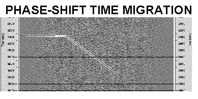
Gazdag or Phase shift migration is a commonly used technique for time migration because it is fairly fast, accurate for steep dips and handles velocity variations allowed by time migration constraints without introducing artifacts. The 3D implementation is fast and accurate for all azimuths. A depth migration solution is also commonly used. The adjacent figures shows the results of the migration for the test synthetic. Click here for an example section migrated with the phase shift migration.
DIP LIMITS: The migration can handle dips up to 90 degrees but may be dip limited to reduce noise. This does not affect run time. The time migration algorithm can be modified to exceed 90 degrees (turning ray migration).
DEPTH STEP SIZE: Is usually selected to be around 20ms. Coarser depth steps may reduce run time, but lead to kinks in steep dips. Some implementations automatically choose depth step based on the chosen frequency range.
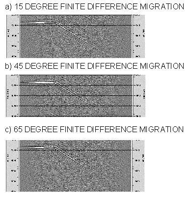
The majority of migrations performed in the past have used finite difference migration solutions despite their general lack of dip accuracy. This is because the methods were efficient and could handle lateral velocity variations with greater accuracy than phase-shift or Kirchhoff implementations. The 15 degree equation is generally considered good up to 35 degrees but on modern systems the 45 degree or 65 degree FX (also called omega-x or w -x) migrations are more commonly used. The approximations inherent within the solution by approximating differential operators with finite differences lead to dispersive noise which accompanies undermigrated energy at steep dips. Dispersion is always present but can be reduced by interpolating data to a finer trace spacing and sampling interval. To reduce dispersion finite-difference migration typically requires the data to be sampled finer than other methods and trace interpolation is almost always required. In this authors opinion finite difference migrations are more trouble then they are worth and should be avoided unless part of a residual migration. Click here for an example dataset migrated with the 15 degree algorithm and here for the section migrated with the 45 degree algorithm.
DEPTH STEP: is the most fundamental parameter for finite difference migrations. Large depth steps cause further undermigration. Around 20ms is the commonest used for time migration, sometimes 2ms is required for steep-dip depth migration. Smaller depth steps do not always increase the accuracy of the result. Some implementations automatically compute the depth step.
VELOCITY ERROR: Because finite-difference migration inherently undermigrates data it is actually more robust to velocity error than other migration types and lateral movements are limited. However, while these may look more pleasing too the eye they are still incorrect.
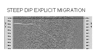
The steep dip explicit time migration solution in PROMAX produces a good result as seen in the adjacent figure and here for the example section. However it is extremely slow to run.
Parameters include maximum frequency and dip. The PROMAX option can also vary memory usage which may speed up application. This type of migration is rarely used by contractors for 2D migration although it is commonly used for 3D post-stack depth migration.