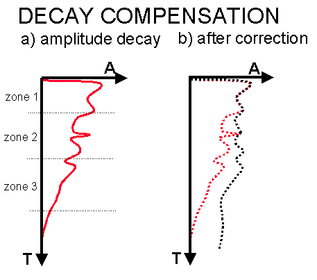
Many types of scaling or gain correction are used during seismic processing. It is essential that the processor and interpreter understand the scaling corrections that have been applied to the data. This is especially so if stratigraphic interpretation or other amplitude related work is to be conducted on the data. In general, as in most processing, it is best to scale the input data only when necessary. Scaling corrections which do not depend on the data are recommended, especially those which can be easily be removed at a later stage. The production of raw sections usually implies the absence of bandpass filter and particularly AGC (automatic gain control) scaling prior to display but this is not always the case and should be checked.
Scaling corrections are often specified in terms of decibels per second. The decibel is a unit of scale defined in acoustics as 20.log(A/B) where A and B are the quantities (in our case amplitudes) in question. If A is twice the amplitude of B this translates to 6dB, a factor of 10 to 20dB and a factor of 100 to 40dB.

Scaling is applied prestack to shot records to compensate for geometric divergence (spherical spreading). Either the velocity dependent divergence correction is used, or more commonly today a power gain is used with t to the power 1.8 to 2.4. An additional exponential correction may be applied to compensate for transmission losses (e.g. 1dB per second held constant after 4s). The velocity factor may be approximately accurate for primaries but tends to overly boost the amplitude of multiple reflections and noise and so reduce the effectiveness of deconvolution. A common solution is to apply power and exponential corrections prestack which are removed following stacking. The correct divergence correction can then be applied post-stack (using a space variant velocity function if required). Geometric divergence compensation is tested using a series of representative shot records which are displayed with various gains applied. That which best "balances" the reflection events is chosen. This effectively reduces the amplitude of the top second and boosts the deeper signal without over-boosting the noise in the deepest part of the record. The choice, as usual, is somewhat subjective. An offset dependent gain is rarely applied at this stage although this is theoretically required for AVO analysis. Offset gains may be more relevant when considering acquisition with a long cable or dual boat operations. Click here for a raw shot record and here for the record following t2 gain correction.
Whole trace equalisation is often applied immediately prior to stacking. The purpose of the equalisation is to reduce the contribution of noisy traces to the stack response. This type of scaling can be very effective at suppressing prestack noise, however should strictly not be applied if AVO analysis is to be performed.
Once the data have been migrated and bandpass filtered they are usually gained prior to display to improve the interpretability of the section by equalising reflection amplitudes. This has traditionally been accomplished by AGC scaling. If the data are to be interpreted on a workstation then the gain tests should also be reviewed on the workstation, and ideally generated on the workstation. Landmark's POSTSTACK may be used for this purpose. AGC scaling should be avoided if possible and replaced by a programmed gain control which does not affect lateral amplitude variation.
The appropriate post-migration scaling should be selected by scaling trials. A section, or more usually a representative portion of section of 500 traces, would be taken and run through a series of scaling trials which should be displayed, ideally side by side, at fixed gain level. The processor and interpreter would use their skill and judgement to pick the optimum scaling for the data. If a time variant scaling is chosen then application windows and window overlap zones will also have to be selected. Merge zones should not be chosen over principal areas of interest. When choosing time-variant scaling it is essential to remember any strong lateral changes in geology in the survey area. It is possible to make the scaling windows follow geological horizons (common for a dipping seabed, but otherwise rare), but this is not recommended unless absolutely necessary. It is also sensible to note that if the data is required to tie other vintages then it is wise to check the scaling applied to these vintages since a mis-match could result in change of character of a target event which could conceivably lead to mis-interpretation.

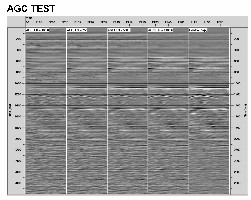
The adjacent figures shows a test of AGC application window length. From left to right the windows applied were 100,250,500,1000, no AGC. Click here for an enlarged display. If too short a window is used (fast-AGC) then relationships between high and low amplitude reflectors will be lost, noise may be boosted and the section will loose character. If too long a window is used then the data may not be sufficiently scaled and some weak reflectors may be lost. Some contractors offer dual window options which can be mixed together in fixed percentages. Typical test values range from 200ms to 2000ms windows. The interpreter should fully understand the type of scaling to be applied to the data.
Is recommended for modern applications, particularly for 3D. The previous discussion for geological variation should be noted.
A gain will generally have to be applied to display seismic data. The commonest way to do this is to find the average amplitude of the first 100 or so traces (or sometimes the whole section) and design a single time-invariant gain compensation which is applied to the whole section. Be careful of some seismic displays which use whole trace equalisation as the default gain type.